IDEA170 · Wesleyan University · Fall 2026
Mechanical
Hopper.
I started with a froghopper’s kick and a goal of jumping forward. Moving the leg from the side to the bottom finally got the hopper off the table. I worked out how to make it wait after I had a jump.
The whole hopper had to jump
- Takeoff
- Build a biologically inspired hopper from the kit. The entire device had to leave a flat surface under its own power. Only fluid or small timing parts could stay behind.
- Delay
- Integrate a mechanical timer or trigger. The jump had to happen between 8 and 60 seconds after the last time I touched the hopper.
- Design process
- Bring hand-drawn sketches to a 20-minute preliminary design meeting and choose a personal design goal. We could revise that goal before the second design review.
- Materials
- We could replenish supplies while prototyping. Final builds had to fit the kit limits, including one 24 × 16 in. sheet of MDF and up to three custom printed parts totaling less than 6 in³.
- Portfolio entry
- Document the prototypes and final build, plot the force measurements used to estimate stored energy, and compare the predicted height with the Celebration jump.
My original personal design goal was a forward hop. I mounted the leg on the side of the body to get that motion. When that layout didn’t work, I changed my goal to getting the whole frame off the table in an upward hop. Throughout both versions, I worked on takeoff first and saved the timer for later.
Borrowing the froghopper’s kick
A froghopper folds its hind legs close to its body. Its muscles load elastic structures in the thorax. When that energy is released, the hind legs drive down together.
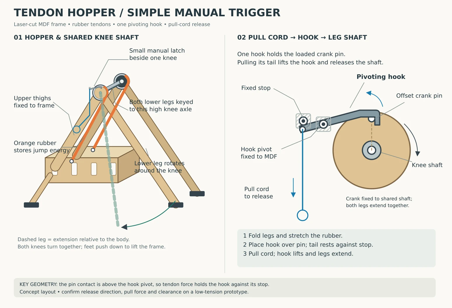
I borrowed the motion of loading slowly and opening quickly. On my hopper, elastic tubing acts like a tendon. It stretches as I fold the leg and pulls the links open on release. The joints swing in one plane, which let me work out the motion on a flat panel.
Getting the leg to push off
Where should each part go?
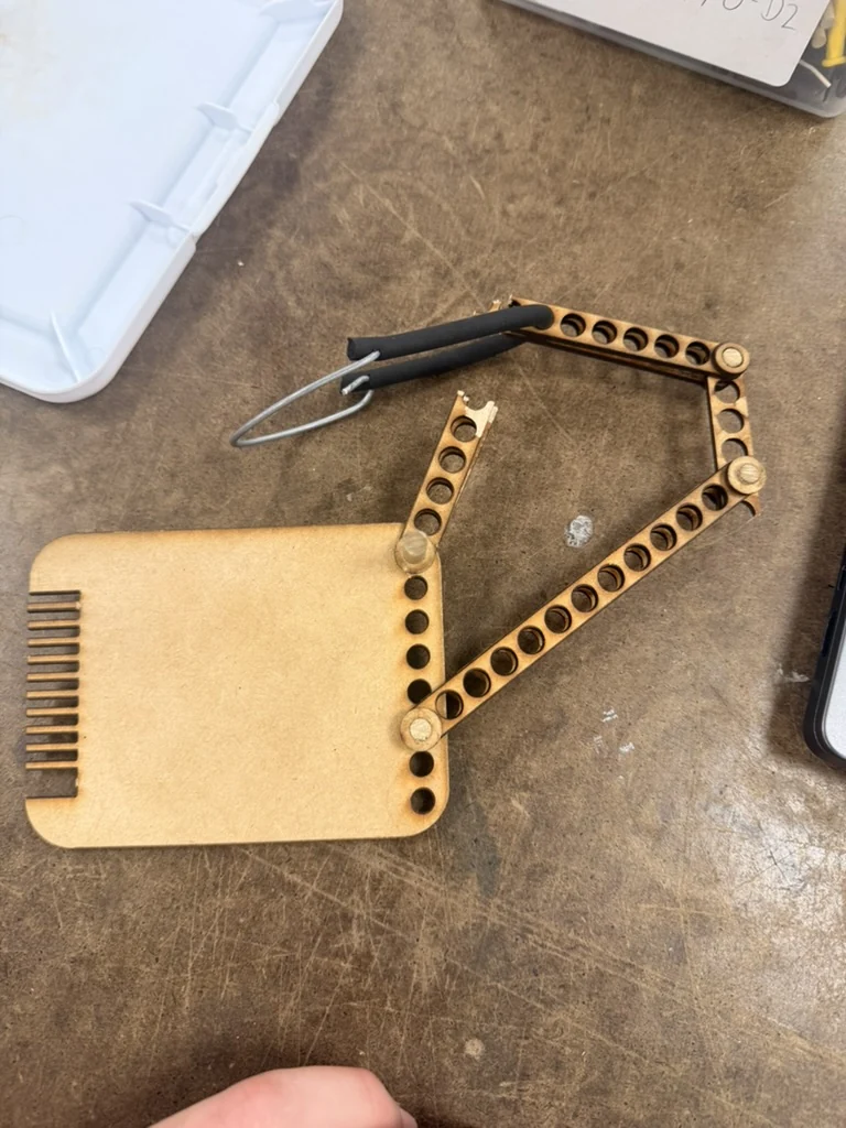
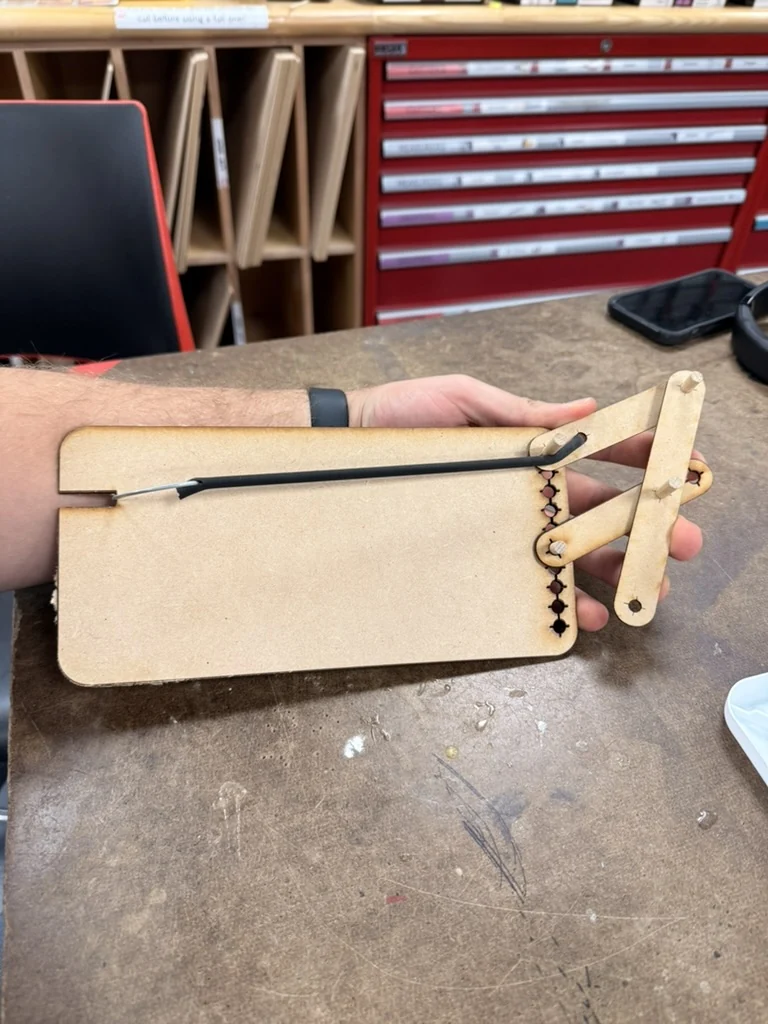
I used the early wooden versions to find a spot for each part. With a row of holes along the body and links, I could shift one pin, fold the leg again, and see how the rope pulled. The same pieces let me compare several layouts.
When the same piece kept snapping
Wood was handy while I was moving pivots around. But one piece kept snapping, and the break in this photo runs right through the end hole. I switched that piece to plastic so I could keep testing the geometry I’d worked out.
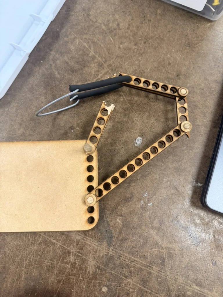
From a side-mounted leg to a foot underneath
In the early versions I mounted the leg on the side of the body to push the hopper forward. I couldn’t get the forward hop I wanted. I flipped the leg to the bottom so it could push down against the table and propel the frame upward.
That change made grip important. If the foot slid out from under the frame, the leg could open without lifting the hopper. I covered the end of the leg with a piece of balloon to help the foot stay planted during push-off.
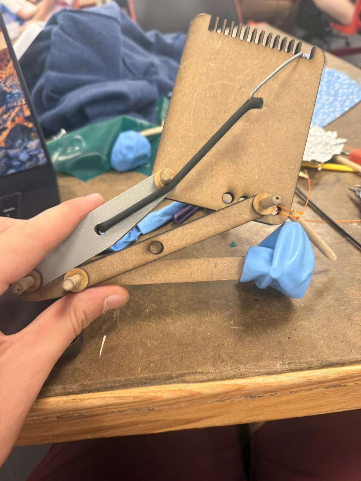
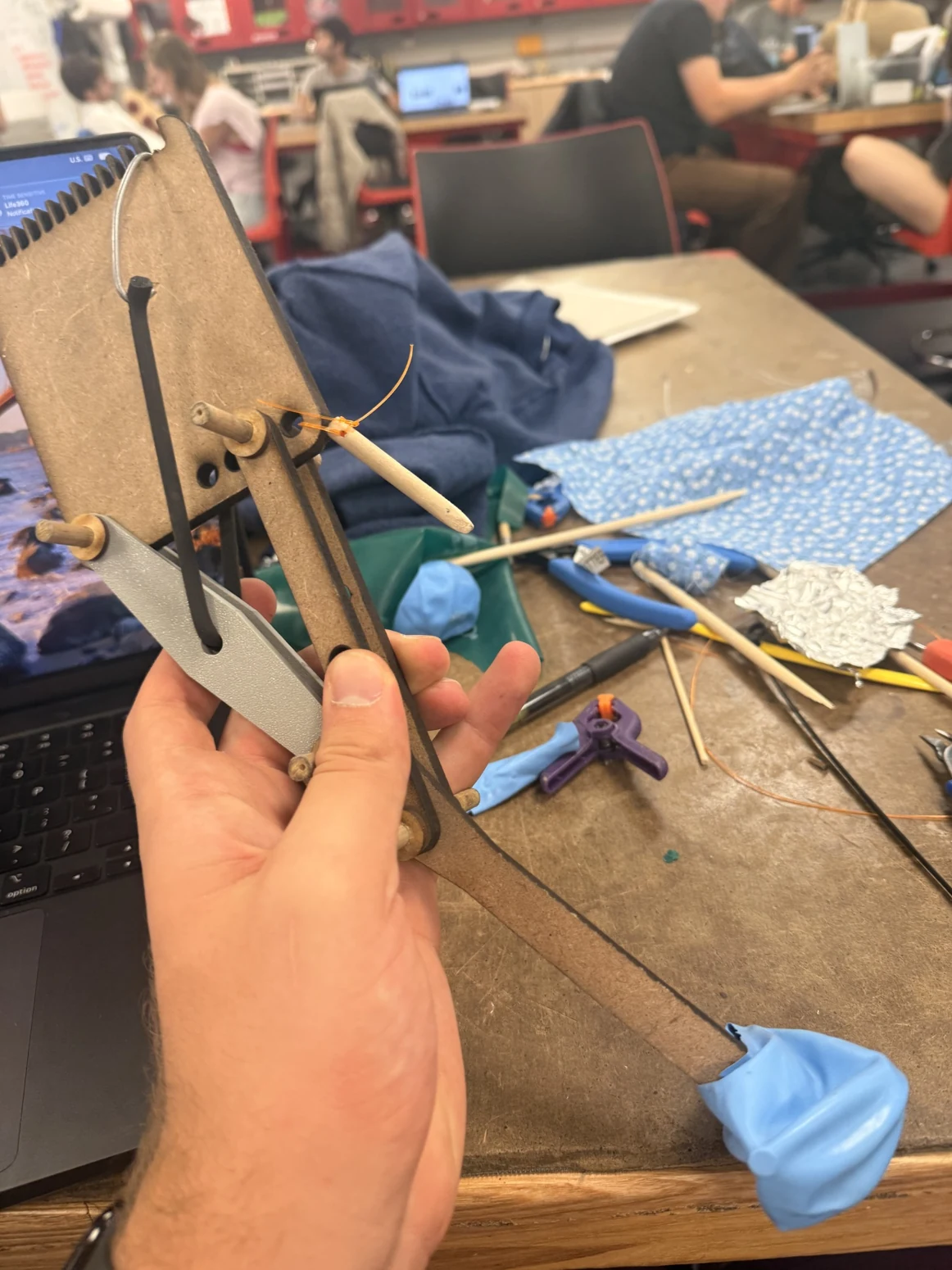
Adding the friction-creep timer
I left the timer until the last minute because I’d spent most of my build time getting the leg to jump. For the friction-creep release, I used fishing line to connect a wooden dowel to the release mechanism. I pressed a strip of the kit’s exercise band against the dowel. Friction slowed the dowel as it slipped, and once it slipped free, the leg opened.
The jump went up and to the right
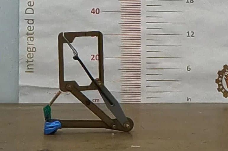
The whole hopper left the table. In the replay, watch the blue foot. It starts under the frame and swings overhead as the body travels sideways. That rotation makes the jump easy to see and its height harder to measure.
Estimating the height from the video
Looking back at the Celebration footage, I estimate the hopper rose 10–10.5 cm above the tabletop. I’m estimating the vertical part of the jump. The hopper also traveled to the right and rotated, so following the blue foot would include its swing around the frame.
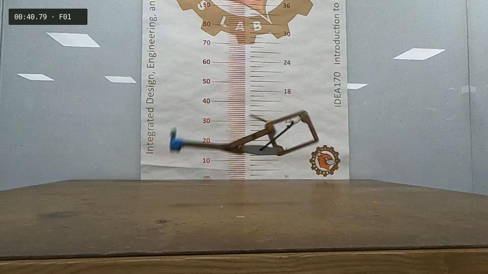
How much energy was in the rope?
My final hopper weighed 94 g. I used one continuous strand of rubber tubing folded at its midpoint. With the tubing folded, the working length measured 10.8 cm relaxed and 12.6 cm with the leg set. Each side of the fold stretched by the same 1.8 cm.
Connecting my measurements to Anders’s test
Anders Nelson measured one straight piece of the same tubing. He recorded a load reading at each extension. Multiplying the load in kilograms by 9.81 m/s² gives the force in newtons. For example, his 370 g reading at 20 mm corresponds to 3.63 N. His last reading, 8.1423 N at 0.050 m, gives a reference stiffness of about 163 N/m.
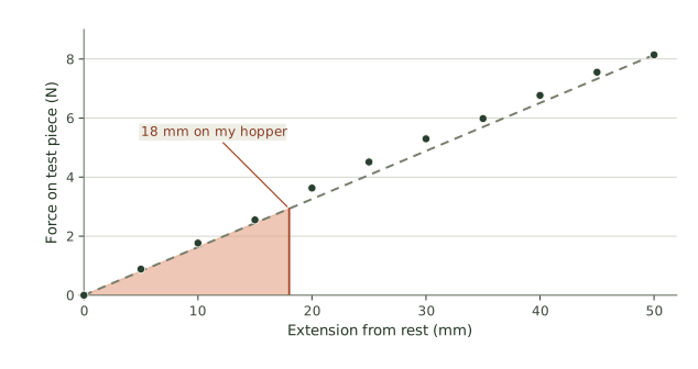
See Anders Nelson’s 11 tubing measurements
| Extension (mm) | Load reading (g) | Force (N) |
|---|---|---|
| 0 | 0 | 0.0000 |
| 5 | 90 | 0.8829 |
| 10 | 180 | 1.7658 |
| 15 | 260 | 2.5506 |
| 20 | 370 | 3.6297 |
| 25 | 460 | 4.5126 |
| 30 | 540 | 5.2974 |
| 35 | 610 | 5.9841 |
| 40 | 690 | 6.7689 |
| 45 | 770 | 7.5537 |
| 50 | 830 | 8.1423 |
The final row uses the confirmed 0.050 m (50 mm) endpoint. The original millimetre column repeats 45 in that row.
Why one folded tube gives a 4× stiffness factor
Each side of my folded tube had half the working length of Anders’s straight test piece. In the linear model, a half-length piece takes twice the force to stretch the same distance. That gives 2 × 163 = 326 N/m for each side. The fold puts the two sides in parallel. They stretch together, so their forces add for a second factor of two. The effective stiffness of my folded tube is 2 × 326 = 652 N/m.
- Working stretch12.6 cm − 10.8 cm = 1.8 cm = 0.018 m
- Stored energy½ × 652 N/m × (0.018 m)² ≈ 0.1056 J
- Ideal vertical rise0.105624 J ÷ (0.094 kg × 9.81 m/s²) ≈ 0.11454 m, or 11.45 cm
I used Anders’s rounded stiffness of 163 N/m throughout. The ideal height assumes all the energy stored in the folded tube lifts the hopper’s center of mass.
Earlier prototype only · October torsion-spring test
My earlier design used a torsion spring. Kamron Ilyas and I recorded seven readings on October 5. At the time the prototype weighed 13 g. The old worksheet’s two-spring prediction of 2.88 m belongs to that build.
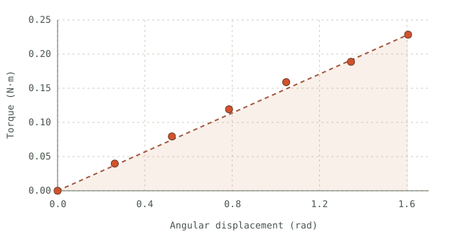
| Angle | Deflection (rad) | Reading (g) | Force (N) | Torque (N·m) |
|---|---|---|---|---|
| 76° | 0.000 | 0 | 0.000 | 0.0000 |
| 61° | 0.262 | 40 | 0.392 | 0.0397 |
| 46° | 0.524 | 80 | 0.785 | 0.0795 |
| 31° | 0.785 | 120 | 1.177 | 0.1192 |
| 16° | 1.047 | 160 | 1.570 | 0.1589 |
| -1° | 1.344 | 190 | 1.864 | 0.1887 |
| -16° | 1.606 | 230 | 2.256 | 0.2285 |
Comparing the jump with the prediction
The assignment compares actual hop height with theoretical height. At the low end of my estimate, 10 ÷ 11.45 × 100 gives 87.3%. At the high end, 10.5 ÷ 11.45 × 100 gives 91.7%. That puts my estimated hop efficiency at about 87–92%. The prediction describes the rise of the center of mass. Judging how high a rotating frame cleared the table from this camera angle limits the precision of that comparison.
Some of the energy stored in the tubing sent the frame sideways and set it spinning. I added the balloon to keep the foot from sliding during push-off. Any remaining slip, friction at the pivots, and losses as the tubing relaxed could also have reduced vertical rise. I couldn’t separate those effects from the video alone.
For a comparable measurement, I’d film side-on with the scale in the plane of the jump and track the frame and leg together. Their masses and positions would let me estimate the combined center of mass in the loaded position and at its peak. I could then divide that vertical rise by the predicted 11.45 cm.
What I’d keep, and what I’d change
I learned that I like prototypes I can change with my hands. Moving one pivot hole at a time let me see what the leg did differently. When the wood kept breaking, I could keep the joint positions I liked and change just the failing piece.
My original goal of jumping forward gave me a layout to test. When the side-mounted leg didn’t work, changing the goal let me flip the leg underneath and work on the foot’s grip. The tradeoff was how little time I left for the timer. The Celebration recording gives me one delay of about 30 seconds. Next time, as soon as I had a leg that could lift the frame, I’d start timing repeated releases and write down the spread. Then I’d know how reliably the timer could meet the rule.